The BRAT Table tool will generate the attributes needed to run the other tools in the toolbox.
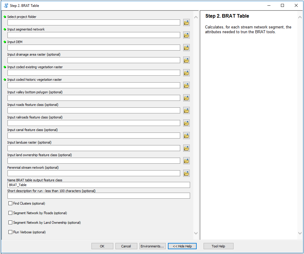
Figure 1: The BRAT Table tool interface.
Required Inputs:
- Select Project Folder - path to the BRAT project folder
- Input Segmented Network - select the segmented (300m) network you created in the preprocessing steps
- Input DEM - select the DEM that you downloaded and created
- Input Coded Existing Vegetation Raster - select the landfire EVT layer, making sure that the “VEG_CODE” field has been added and populated
- Input Coded Historic Vegetation Raster - select the landfire BPS layer, making sure that the “VEG_CODE” field has been added and populated.
- Name BRAT Table Output Feature Class - select a location and name for the output line network which will include the necessary “iGeo”, “iVeg”, and (optionally) “iPC” attributes to run the model.
Optional Inputs:
- Input Drainage Area Raster - if you want, you can derive a drainage area raster from the DEM beforehand. If you do so, select it here. If you do not do so, the BRAT Table tool will automatically derive one, which will make the run time longer
- Input Land Ownership Feature Class - Land ownership polygons can be provided for identifying land ownership per reach and distance to private land.
- Perennial Network - A perennial network can be given to populate the
IsPerenfield. If a stream network is given here, only perennial streams are used to find multichannel sections of the stream network. This may make it easier to edit the output for the Braid Handler. - Short Description for Run - Write a short (less than 100 characters, including spaces) description for the BRAT run to be included in the project XML file.
The following inputs are optional but required to run the Constraints and Opportunities Model
- Input Valley Bottom Polygon - select a valley bottom polygon that is associated with the input stream network
- Input Road Layer Feature Class - select a feature class representing all roads within the study area
- Input Land Use Raster - select the land use raster, making sure that the “LU_CODE” and “LUI_CLASS” fields have been added and populated.
- Input Railroad Feature Class (optional) - select a feature class representing all railroads within the study area (if present)
- Input Canal Feature Class (optional) - select a feature class representing all canals within the study area (if present)
In addition, there are checkboxes that change the behavior of the tool in minor ways.
- Find Clusters - This option will create a
ClusterIDfield and populate it. This field is used in the Braid Handler to modify drainage area values. By creating them in the BRAT table, the technician can modify clusters to fit with what they want the tool to do. This is an advanced editing option, and not necessary for most users. - Segment Network by Roads - This option divides reaches based on the roads input. This can be useful if the user wants to compare the results of the model to field data collected from upstream and downstream of bridges. This can be useful in the field, but is not recommended for other uses because it creates arbitrarily small network segments which bias any calculations based on length (e.g. slope, density, etc.).
- Segment Network by Land Ownership - This option divides reaches based on the land ownership boundaries. This can be useful if the user wants to compare the results of the model along hard boundaries, otherwise the model will calculate land ownership parameters based on the center of the segment. Again, this is not recommended for other uses because it creates arbitrarily small network segments which bias any calculations based on length (e.g. slope, density, etc.).
- Run Verbose - This option enables ArcMap to provide messages for each step conducted by the tool, letting the user track progress as the tool runs.
Click OK to run the tool. If the project folder you gave does not contain an Outputs folder, the tool will create one. The tool will then create an Output_## folder, where “##” is the next available number. The tool will then create an 01_Intermediates file in the Output_## folder that it created. The tool will then copy the stream network given into the 01_Intermediates folder. This copy will be where all the data from the other inputs is stored, including the iGeo, the iVeg, and iPC attributes. This is the data that will be used to inform the rest of the model.
The tool will also create several folders in the 01_Intermediates folder. The first created will be a folder with the buffers used to bring the data into the BRAT Table. The folder will be named ##_Buffers. This folder will contain a 30m buffer and a 100m buffer, as well as a layer for each. The next folder will be called ##_TopographicMetrics, and will contain layers symbolizing data about the slope and drainage area of the BRAT Table. The third will be named ##_AnthropogenicMetrics, and will contain layers symbolizing data about the distance to canals, roads, road crossings, roads in the valley bottom, railroads, land use intensity, land ownership per reach, and distance to private land (priority beaver translocation areas). This folder will not be created if no conflict or land ownership inputs are given. The fourth will be named ##_Perennial, and contains a layer showing what streams have been marked as perennial and which ones are non-perennial.
 Back to BRAT Home